Intellectual
Foundations of UI Application Development
There is much discussion about the best way to build an application. Is J2EE better than .NET? Where does the business rules approach fit in? Should business rules be implemented in the database or in the middle tier? Should we use a Model 1 (traditional) or Model 2 (Model-View-Controller) architecture? Should we use a waterfall or Agile techniques in development?
What we lack in these discussions is
Modeling a System
The question to start with is: What are we modeling? Since their inception, modeling languages and tools have focused mainly on trying to model “computer things” rather than real-world things. One of the early modeling devices, flow charting for programming, was a diagrammatic representation of the program itself. As a result, flow charts were of little use to most people in the IT industry other than for occasional white board discussions. Flow charts written after the programs were already created as part of a college course were usually more difficult to read than the programs themselves.
For the past 20 years, database designers have been creating databases using some type of entity relationship diagram (ERD) data modeling tool. ERDs have proven more suitable for logical descriptions of systems, but still fall short as a logical modeling tool. ERDs only provide enough grammar to describe what can be easily implemented in a relational database. Even obvious things that should be included in a data model (such as derived attributes) are missing from ERDs because there is no easy way to implement them in a relational database.
Most well-designed relational database systems employed tools such as Erwin and Oracle Designer. Using these tools, the diagrammatic representations were useful in helping build the system. Looking at a data model enabled us to grasp relationships within a database and intuit the corresponding tables, columns and foreign key constraints. However, from a system design perspective, data modeling only helped to solve a small percentage of the problems. Even the most data-centric architect would not assert that only a good data model is needed for system design. The model itself does little more than imply the process flows of the underlying objects that it represents, nor does it provide much information about how any applications interacting with those objects will work.
Structurally, data models do not provide complete information about the objects they model. Using the simple Departments and Employees example, it is clear that employees work for departments but the model does not show information such as “Departments with employees must have at least one manager” or how employee information should be displayed. The reason that this information is not contained in the data model is that there is no easy way to generate this information to a relational database. Therefore, the tools were limited to modeling only those things that could easily be generated. In general, modeling grammars are limited to what it was possible to generate.
The Unified Modeling Language (UML)
The Unified Modeling Language (UML) suffers from a similar
code-centric philosophy. It was designed by object-oriented (OO) programmers
with the goal of creating OO programs. For example,
A Different Way to Think About Application Development
The goal of a logical model is to communicate the modeler’s understanding of the system to users. Since most logical modeling tools do not generate systems or only generate to another model type, it doesn’t much matter if the models are precise or correct. It only matters that they facilitate communication between IT professionals and users. For example, logical data models are often created to show to users. These models are then transformed into physical models in order to formally specify table, column and foreign key constraint names.
This paper represents a different way of thinking. It will not focus primarily on modeling a physical computer system. There will be no object in the modeling grammar called a “table” or “procedure.” Instead, discussion will center on objects, their structures, and how they behave. The data validation rules associated with these objects will also be discussed along with applications. Applications in this case mean the screens, visual elements associated with these screens, and how the visual elements represent the system objects. Rules for moving from screen to screen in the user interface and what happens in between each transition will also be discussed.
A J2EE system architecture, Struts page flow diagram, or even a relational database is not assumed. XML may someday become a strong enough data source that relational databases are no longer needed. Regardless, the system requirements and the logical description of these requirements will not change.
This paper describes the structure of a formal grammar designed to fully articulate a system, independent of any technology.
Complete Description of the System
A complete logical description of the system includes enough information to generate the entire system. This includes the database, code required to enforce object process flows, as well as the user interface itself.
It is not always possible to go directly from the logical specifications to the completely implemented system. There are always some gaps and missing pieces that are specific to the technology to which the system is being deployed. The system generators can make reasonable but not necessarily optimal decisions. Once the logical specifications are complete, some additional percentage of elements will need to be specified before generating the system. The goal is to keep this additional portion of system elements to a minimum.
There are many advantages to this approach:
1. The logical specification of the system is much more user-friendly. Users are able to participate in the design process.
2. Systems can be created more quickly, easily, and at less cost.
3. Specifying, modifying, and maintaining business logic is much easier since all business rules are stored in a repository.
4. Easier and swifter response to changes in technology. Typical systems have many millions of lines of code which can be changed much more easily using a code generator.
This approach is not without tradeoffs. Model-driven development (MDD) using generation is a very different way of thinking about system development. It requires a discipline and architectural approach that many developers are not comfortable with, as well as a team of system designers who are familiar with a rules-based way of thinking.
Does this approach make sense? Many of the pundits in the OO community are skeptical. They remember the unfulfilled promises of the CASE methodology. At Dulcian, we have been using this approach for almost a decade, evolving better and better tools to support this way of thinking. At this point, it is possible for us to generate over 99% of a system directly from one or more repositories.
The taxonomy shown here does not presuppose an MDD philosophy. It is a structural roadmap of a system. The framework evolved as part of the intellectual underpinning of a rules-based, near 100% system generation product (Dulcian’s BRIMÒ), but this discussion is relevant to the evaluation of any product or system development philosophy.
The Taxonomy
Most of this taxonomy has evolved from Dulcian’s work with business rules-based systems over the last decade. The business rules approach is about describing and generating systems. This taxonomy is the foundation for discussing system architecture using a business rules approach.
I. System
A. Logical
1. Object
a. Structure
b. Process
c. Validations
2. UI
a. Model
i. Structure
ii. Binding to objects
b. View
i. Structure
ii. Logic
iii. Presentation
c. Controller
B. Implementation
1. Persistence layer
a. Objects
b. Code
2. UI layer
a. Model
i. Objects
ii. Code
b. View
i. Objects
ii. Code
c. Controller
i. Objects
ii. Code
II. System Interaction
A. Logical
1. Object Mapping
B. Implementation
1. Interface Objects
2. Code
Systems and their Interactions
The first level of the taxonomy divides the world into systems and the interactions between them. There should be little argument about this separation. The only implication is that system interactions can be isolated.
The traditional (pre-Service-Oriented Architecture) practice of providing database links between systems is intellectually unsound. Systems should be isolated from the ways in which they communicate.
Many systems themselves can be isolated into several systems that have their inter-system communication separated out. For example, in a Human Resources system, users can fill out images of paper forms on their computers that are then uploaded into the database. Each form can be considered as an isolated system that generates an XML file. These files are then sent to the main system for processing. In this way, the logic of the forms is isolated from the rest of the system.
Logical versus Implementation
This distinction should also raise few objections, but it is surprising how few product architectures (even ones with an expressed “business-rules based” philosophy) embrace this idea.
The idea is to specify the system in an implementation-independent way and then, in a separate step, decide what to do with that system description. This philosophy gives rise to the motto “The articulation of the rules is independent of the implementation of the rules.”
Most products ignore this idea and straddle the fence. For example, the Oracle Application
Development Framework – Business Components (
In the case of JDeveloper, ignoring the distinction between logical and physical is appropriate. JDeveloper is an implementation tool. It is trying to provide developers with a quick and efficient way to implement an architectural vision. With business rules products, this direct-to-code approach is inappropriate. One of the greatest advantages of a rules approach is that it describes the system from the user’s perspective. It ought to then be possible to implement that representation in a variety of different ways. As technology evolves, it should be easy to refactor the rules to support those new technologies.
In tools that cater explicitly to the system architect, this logical/physical separation is implemented quite cleanly. Both Oracle Designer and IBM’s Rational Rose allow users to specify large portions of the system and then generate those parts of the system.
This division between logical and implementation is not without problems because the two have to be kept in synch. Maintaining two (or more) models makes it nearly impossible to keep them synchronized. This is a problem that is very familiar to database designers. Anyone who has used a tool that generates a data structure (like Oracle Designer) is aware of the practical difficulties of keeping the model and database in synch. With Designer, the situation was even more difficult since the tool supported both a logical ERD as well as a loosely coupled physical data model which was used to generate the actual physical database. Therefore, using Designer, there are three representations of the database. When changes were required or errors discovered, they potentially had to be dealt with in all three places.
In a waterfall methodology where the design progresses in an orderly fashion from logical to physical to development, this tool worked very well. But once the system was in place, it was a very difficult architecture for system maintenance.
The problem arises from using the logical model to generate the implementation model and then allowing independent manipulation of the implementation model. There is nothing wrong with the idea of having both a logical and physical model, but trying to maintain multiple models is usually impractical.
The solution is to tightly couple the logical and implementation models. Rather than having an independent logical and physical model, instead, you specify what is “logical” (implementation-independent) in the logical model and only specify implementation-dependent things in the implementation model. You can allow for limited overriding of the algorithm used to generate the physical model and keep track of what was overridden, so that element changes in the logical model can be updated to the physical model. This tight coupling of layers is an important concept.
Logical Specification of a System – Objects and User Interface
When logically specifying a system, the idea is to partition rules into those about objects that will be true for any representation of those objects and rules that are UI-dependent. Few existing products divide the rules in this way.
It is clear that if you know a lot about the objects in the system that you also know much of what you need to build the system. For example, in the Employee class, there is an attribute “lastName” that is required and is 30 characters in length. Any UI representation of last name that is editable should be a text box that will hold 30 characters and it should have a “required field” indicator. The UI standards will indicate the color, font, etc., but once the standards are in place, the developer should not have to make any decisions other than where to place the field on the screen. It should not be incumbent upon the system designer to specify that the attribute is required at the UI level. All that should be necessary is an indication that this text box is an editable representation of the object attribute so that the object level rules (length, required, textual validations) apply.
The more you know about the objects, the less you need to specify anything other than these objects. The system design proceeds much more smoothly if you can create UI-independent rules at the object level. Then any UI representation of that object will inherit its rules. It makes no sense to specify rules for the object and then re-specify those same rules for each UI representation of the object.
A. Object Rules
Object-level rules are where most of the design of the system takes place. This idea should be the core of our thinking about application development. Traditionally business rules about the objects are not even captured coherently let alone coded so they are clearly attached to the objects.
Rules associated with objects always comprise a large portion of the total system rules. Many people think of object rules as only as those that are contained in the data model. While it is true that object rules will define the data structure of the database, these rules can specify much more than what is contained in a traditional ERD. For example, the logical process flow for handling an object such a purchase order can be defined at the object level. The process should also be independent of any particular representation in the user interface. Data validation rules such as “any contract actions should take place between the start date and end date of the associated contract” should be articulated with the object so that any representation would conform to the rule.
B. User Interface (UI) Rules
If rules are placed at the object level, why are additional
rules needed at the user interface level? It is possible to generate an entire default
user interface based solely upon knowledge of the associated objects. However,
what is generated will not be particularly user-friendly. There are additional
rules that are concerned more with the needs of the user that are not properly
associated with system objects at all. For example, determining which
attributes will be displayed in what positions on the screen, what areas of the
screen are automatically populated when the screen opens, whether or not rules
are validated when tabbing out of
C. Where should the rules be defined?
The division between object rules and UI rules is not always
clear cut. Occasionally, there are rules encountered that could be placed in
either category. For example, in an address object with COUNTRY and POSTAL CODE
attributes, at the object level, the COUNTRY and POSTAL CODE should be
consistent. However, in practice, changing the COUNTRY from
If UI rules are attached to the objects themselves and overridden in the representation of the object, full object-oriented (OO) thinking must be used in designing the repository. This renders the repository more difficult to use, especially for non-IT professionals. If a rule structure is too complex for users to understand, there is little reason to include it in the repository.
It is still a good idea to always try to define rules that are universal across all representations of an object at the object level. Only additional UI-specific rules should be defined at the UI level. Most of the rules required to define an application occur at the object level. In practice, the division is approximately 80% object rules and 20% UI rules.
D. Object Rule Types
Object rules can be subdivided into Structural, Process and Data Validation rules. It is important to remember that these rules by their nature do not divide into these three classifications. These are three different and arbitrary ways to describe object rules. For any given rule, it is usually most convenient to articulate it using one particular mechanism, but most rules can be articulated using more than one mechanism.
1. Structural Rules
Structural rules describe the static nature of the objects in the system. What are the objects of interest? What are the attributes associated with them? This is the kind of information that is traditionally captured in ERDs, although in recent years, UML class diagrams have become more widely used for diagramming systems.
UML Class diagrams (with some extensions) are somewhat better suited for structural modeling than ERDs. ERD proponents argue that UML is an implementation tool and that cannot be used for logical modeling. UML proponents argue that ERDs are too limited and do not support inheritance well enough. This debate is beyond the scope of this paper but the choice of diagramming syntax is of far less importance than deciding what should be captured.
Data modeling has traditionally only been concerned with capturing the information required to generate the tables, columns and constraints for the DBMS. Structural rules include a much broader range of information than that limited scope. Structural rules should include the following areas not traditionally included in data modeling:
1) Derived attributes
2) Objects defined using other objects (for example, to generate database views)
3) Audit, security, and history requirements
4) Default object display
5) Triggering events based on Insert, Update, and Deletion of objects or attributes
The idea is to partition all of the rules required to specify a system, and not simply identify the rules necessary to generate the database. Focusing on database generation rather than on the structure of the objects is a primary reason for the limitation of CASE tools such as Oracle Designer. Rather than thinking about capturing rules of a specific type (i.e. structural), CASE tools focused on the purpose (i.e. generating a database), hence the tools never evolved into full system specification tools.
For the structural rules area of the repository, imagine a standard UML class diagram meta-model as shown in Figure 1. Of course the real model would be more complex, but for the purposes of this paper, showing the key classes is sufficient.
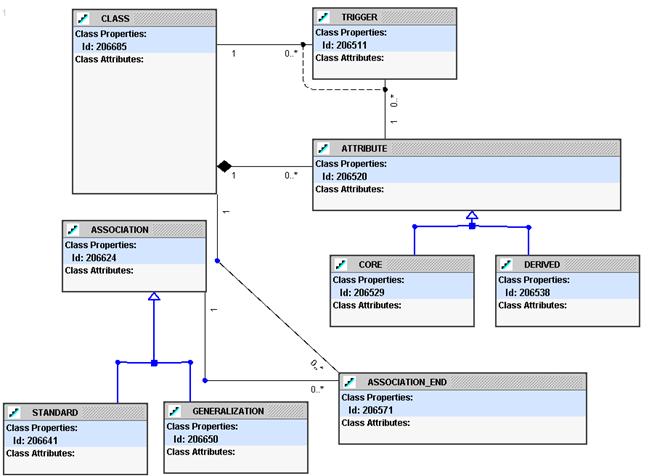
Figure 1: UML Class Diagram Meta-Model
NOTE: The only part of the model that may seem odd is having “association end” as its own class. This allows generalizations to have one head end class and multiple end classes.
2. Process Rules
Process rules define the process flow of an object from one state to another. A particular object may have states associated with different aspects of the object. For example, a person may simultaneously have a physical health as well as an economic health. One could define independent process flows for each aspect.
Process rules should be described using some type of flowchart or process flow rather than a declarative mechanism. There are simply too many rules associated with an object to be able to manage without dividing the object flow into states. If process rules are specified using a declarative mechanism, you end up having thousands (or even tens of thousands) of rules. These rules interact, may cancel each other out, and are impossible to manage.
Traditional State Transition Engine (STE) diagrams or flowcharts are similarly hard to manage. You might remember university classes in programming where you were forced to create flowcharts to document your programming assignments. You always wrote the code first and the flowchart afterward. The flowchart for a simple 200-line program had 60-80 little boxes on it and the flowchart was harder to read than the program code itself.
The solution to making an
The formal structure used is to add the idea of an “event” on a state (similar to the idea of a database trigger on a table). When the event is triggered, actions can be executed. Rules can be attached to an event to prevent it from occurring (for example security to prevent an object from being opened).
States are associated with a class of object. Process flows are not independent things. The process flow defines the allowable states for a particular class of objects.
The high-level process flow repository model is shown in Figure 2.

Figure 2: Process Flow Repository
3. Data Validation Rules
Data validation is a complex topic in its own right. A system may easily contain hundreds of data validation rules. These rules may always need to be enforced or only contingently enforced based upon some condition or state of the object. The rules may only require looking at the object being validated or accessing objects in other classes. Rule failure may only trigger a user warning or may prevent data modification entirely.
The difficulty is in creating a grammar to help specify the rules. Natural language is not precise enough and code is too hard to read. The solution is to place the rules at the object level but support an Object Constraint Language (OCL)-like syntax that allows you to validate across classes. For example, the rule to say that a department must have at least one employee (in the standard EMP/DEPT 1-to-many model) would be written as:
:_child.emp.count >= 1
This grammar can be easily extended to support 99% of all rules encountered.
Validation rules are often only contingently required. Therefore, these rules can be invoked at the object state level and may be contingently executed based upon some condition. The high-level model to support the data validation repository is shown in Figure 3.
Figure 3: Data Validation Repository Model
E. User Interface (UI) Rule Types
Once the object rules are collected, there are some additional rules required to specify the UI. For the purposes of this discussion, the UI rules will be kept to a minimum so that rules described at the object level will not be repeated at the UI level.
The model-view-controller (MVC) pattern architecture itself will not be discussed here nor will the decision to use it be defended. However, the author’s perspective on MVC may be slightly different than the industry standard in that it is viewed as a logical design pattern, and not simply a way to write code. The goal here is to define the application independent of any technology or implementation considerations.
1. Model Layer
The model portion of the logical UI rules is not difficult to specify. There is already so much information at the object level that little extra information is required at the UI level. Classes, attributes and associations have already been defined at the object level. As a result, the only requirement at the UI level is to select a subset of objects (classes, attributes, associations) from the object level for use in the UI specification. This approach runs counter to the way in which most systems are built. Most tools specializing in model development support very sophisticated object specification in the model portion of the UI. This approach does not preclude a “thick” UI model level for implementation; it merely implies that the structure of the UI model should properly be defined at the object-level.
Using this approach means that the structural rules at the object level will be quite sophisticated, requiring not only standard views, but also views that are dynamically altered or generated based on the values of some passed parameters. All that remains for the UI model specification is to point to existing structural object specifications. The model to support this is shown in Figure 4.
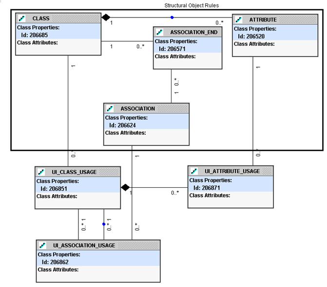
Figure 4: UI Model Specification
2. View Layer
The rules in the view layer of the logical UI are themselves divided into structural (the elements and how are they grouped), logical (what happens when a screen opens, or a button is pressed), and presentation (how and where the elements are displayed).
The view layer structural rules are very simple. They define the UI elements (fields, buttons, etc.) and how they are grouped and bound to the UI model.
On the other hand, the view layer logical rules are quite
complex. A full Event-Condition-Action (
Figure 5:
Presentation rules are simply attributes of UI Element Group and UI Element. The tricky part here is that different products use very different methods to describe the layout presentation. The Oracle Developer tool uses X and Y position, whereas HTML uses tags that automatically position themselves on the screen. Trying to come up with a technology-independent way to describe layout is not a problem that is currently well handled.
3. Controller Layer
The real strength of the MVC design pattern is the
Controller layer. This layer can be
partitioned into rules controlling screen navigation and what happens during
these screen transitions. The Struts controller should not be used to logically
define rules. This is too restrictive an
implementation and would force a redesign if/when JavaServer Faces become the
standard. The Controller layer is a natural place for using the same type of
By using a technology-independent way of describing page flow, you can generate the system to Struts, JSFs, or any other platform.
Physical Specification of a System
Once the logical specification of the system is complete, it is necessary to specify the physical structure of the generated code. This is a standard metamodel that conforms to the way in which you want to build your system. The appropriate model will vary depending upon the technology, so a discussion of appropriate models is beyond the scope of this paper.
Obviously, generated elements will be linked to their generating counterparts. Also, a good design decision is to limit the extent to which overriding generated elements will be allowed. For example, in a generated database, overriding tables and column names so that they are different from class and attribute names would make the Object Structural class diagram next to useless and should be avoided.
System Interaction (Mapping)
System interaction is how we define rules associated with data migration (ETL), web services and similar situations where one set of objects must be mapped to a second set. The association need not even be to an actual system. System interaction rules can also define how the various systems map to the virtual operational data store (VODS).
The usual way in which this mapping is supported is to take one source object class at a time and describe how it can be transformed to a target class using a process flow metaphor. This is how Informatica and Oracle Warehouse Builder approach the problem.
The other way is to describe complex sets of information in a master-detail structure and then describe how to map that complex structure. This way of thinking does not require a process flow and usually results in code generation that runs more efficiently.
System interaction should be defined on the generated objects (but not necessarily database tables), and not on the logical objects. The mapping is actually done to elements in the repository so that if the element names change, the mapping code can be automatically regenerated.
This is one of the most versatile ideas described in this paper. The same structure is used to generate code for many different purposes and architectures.
The basic mapping model is shown in Figure 6.
Figure 6: Mapping Model
Conclusions
The taxonomy described in this paper can be used as a way to talk about applications, application development environments and development architecture. There have been many times where a confusing discussion was simplified by saying something like “Let’s first talk about systems then discuss how to make them integrate” or “That isn’t an object rule. That is a UI thing. We are focusing on the object rules right now.” This paper does not suggest that the work presented here can have the same kind of impact as the Zachman Framework or the Nolan model, but it does help serve as a foundation for the architectural discussion surrounding application development.
About the Author
Dr.